|
Note: I no longer recommend this solution. "Proper" solutions are now much cheaper, and increasing monitor resolutions have decreased the acceptableness of this solution. Here's an example of a poper solution. It's possible to send a VGA "video" signal down an ordinary Cat-5 ethernet cable. This is possible for two reasons: firstly, although VGA connectors have 15 (or 13) pins, only about 8 wires are actually necessary to send the VGA signal; and secondly, ethernet cable is twisted pair, and we can use the magic of twisted pair to push the analog VGA signal further than spec. |
|
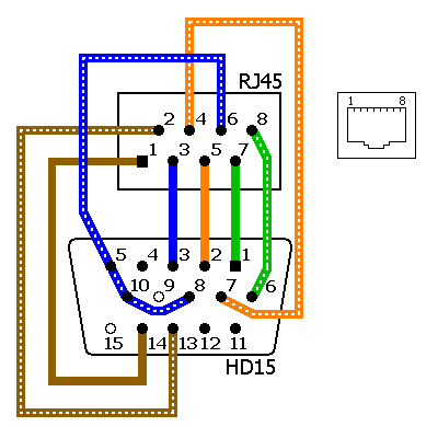
The diagram above shows conversion from HD15 (VGA) to RJ45 (an ethernet socket). A similar adapter is used to convert back again. Connectors are shown from the solder side. This diagram assumes your Cat-5 cable is crimped in the standard way (not as a cross-over cable). This is nifty because:
Standard VGA extension cables come in lengths of 1.8 metres (6 feet), and if you need to go a bit further you can daisy-chain several of these, with a little signal loss. You can also get a super-special low-loss 30 metre (100 foot) VGA extension cable, but they're very expensive and very hard to find. Additionally, their fat VGA plug ends won't run through conduit smaller than about 50mm. I've run VGA over Cat-5 for distances of about 15 metres (50 feet). At this range, the 800x600 screen looked fine when it was displaying a coloured background; although when it was displaying black, a lighter gray region was visible, probably due to interference from the synch signals. Your mileage will vary depending on screen res and refresh rate (lower will go further), contrast and brightness in the image (high contrast and brightness will go further), and interference from other sources (running the cable in its own metal conduit is best; if you're not in conduit, running parallel to other cables is bad). This trick will work equally well with Cat-5e and Cat-6; possibly even a little better. There are two easy ways to implement the above diagram:
Etch circuit boards |
|
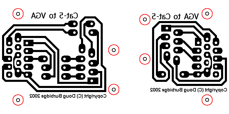
Above is artwork for two adapters, on single-sided PCB. On the right is a male HD15 to RJ45, to plug into the back of your computer. There are three "components" on the board: the HD15 connector, the RJ45 connector, and a wire link. For the monitor end, you can use the board on the left, which has an RJ45, a female HD15, and five wire links. Or you can simply use two of the male HD15-to-RJ45, plus a female-female VGA gender changer. Print at 300 dpi. The artwork is shown here from the component side -- print it onto transparency film, and then flip the transparency over so that the text runs the correct way. There are nice wide tracks with wide gaps between to allow easy etching; and nice big solder pads to allow easy drilling and soldering. The very thin "solder pads" are merely drill guides. Use an RJ45-to-DB9 adapterBuy an RJ45-to-DB9 adapter like this. Throw away the DB9. Cut off the nifty little pins that insert into the DB9. Buy a "solder cup" HD15 connector of the appropriate gender. Strip back a little of the wires leading from the RJ45 socket, and solder them onto the HD15. Then do all this again, for the other gender. You now have a matched pair. |